DFS - Mining
Bosnian Definitive Feasibility Study
13 September 2021
The 2021 DFS mine plan was produced by Mining Plus, with input provided by Paterson and Cooke on the backfill.
Major Changes to the Mine Plan from the 2020 PFS
Modified Underground Mine Plan
The 2021 DFS mine plan is focused on mining the high-grade sections of the Rupice deposit as early as possible and providing consistent high-grade feed to the Vares Processing Plant for as long as possible. As a result, the previous mine plan was modified to accommodate a new lower (ingress) and upper (egress) declines for optimised access, which also improves operational flexibility and safety.
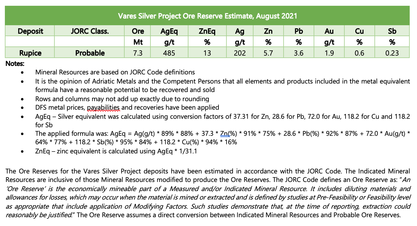
The Ore Reserve tonnes of Rupice have decreased from 8.4 Mt to 7.3 Mt, while the new Ore Reserve grade increased from 463g/t AgEq to 485g/t AgEq. This was due to the application of updated NSR cut-offs by ore type determined during geo-metallurgical domaining and metallurgical testwork. The average dilution factor increased from 10% to 13%, taking into account the potential spalling of backfill from adjacent primary stopes when mining secondary stopes.
An additional third decline will be built, replacing the previously considered raisebore, dedicated solely for ventilation. Use of a ventilation decline rather than the vent-raisebore removes the risks associated in the near-surface ground conditions and provides an improved emergency egress. The third decline can also provide additional access for ore-haulage later in the mine life by relocating the ventilation fans.
Removal of Veovaca open pit from the mine plan
The Vares Processing Plant has been designed around the ore from the Rupice Underground Mine, as this is the highest value ore. Processing of ore from the Veovaca open pit, without modifying this process design, is anticipated to produce concentrates with marginal project economics. Further metallurgical test work and engineering will be undertaken to better understand how a higher value concentrate can be produced. Therefore, it was decided to defer the Veovaca open pit from the 2021 DFS mine plan.
Ore Reserves
The Ore Reserve Estimate was prepared by Mining Plus and comprises Probable Reserves as shown in table 14 below:
Table 14: Vares Silver Project Ore Reserve Estimate
Mining Production Rate
The Rupice Underground Mine production rate is designed to match the nameplate capacity of the Vares Processing Plant at 800,000 tonnes per annum.
Stope development of the Rupice Underground Mine will start eight months prior to the commissioning of the Vares Processing Plant. This will ensure sufficient ore is available in the surface stockpiles at the Rupice Surface Infrastructure for a consistent and optimal grade of feed to the Vares Processing Plant during commissioning and ramp-up. This provides considerable versatility and reduced risk during commissioning and early operations. Starting commissioning on ore other than high grade is preferable and as operations ramp-up so it will be possible to increase the feed grade as confidence builds and plant operating stability is achieved. At the time of starting commissioning, there will be approximately 210,000 tonnes of high-grade ore, 190,000 tonnes of medium-grade and 26,000 tonnes of low-grade ore – in total about six months at full production. During the mine life, sufficient ore is produced to maintain the Vares Processing Plant production rate, with excess lower-grade ore being stockpiled for treatment later in the mine life. During the later stages of the mine life, the underground production rate drops off due to reduced stoping areas being available and the cyclic nature of the cut-and-fill mining methods.
Mining Method
Access to the underground workings will be via two declines developed from the surface accessing the orebody via further development of ramps, level access drives and footwall drives. All the development access will be suitable for trackless equipment.
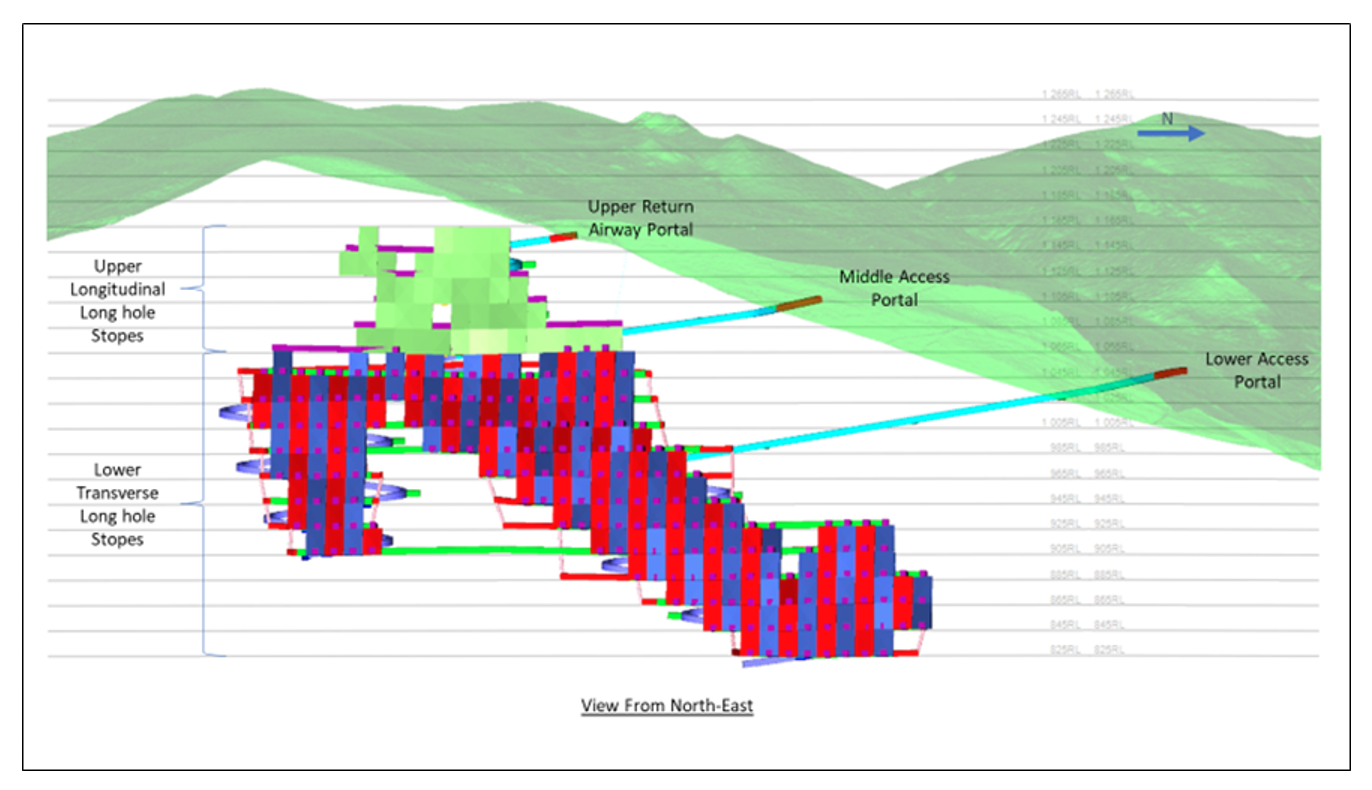
The underground stoping will be divided into two main mining method zones as follows and as shown in in the mine plan in Figure 3:
- Transverse Longhole Open Stoping zone (“TLOS”)
- Longitudinal Longhole Open Stoping zone (“LLOS”)
The TLOS zone will be below the 1,065 level and the LLOS zone will be from and above the 1,065 level.
TLOS will be used in areas where the ore zone thickness is greater than 20 m. Stopes will be oriented in a transverse fashion with stope access drives orientated from the footwall towards the hanging wall, perpendicular to the general orebody strike.
LLOS will be used in areas where the ore zone thickness is less than 20 m. Stopes will be oriented in a longitudinal fashion along a strike drive.
Primary stopes represent the initial phase of production mining within the TLOS section of the mine. Primary stopes are mined in a “chequerboard” fashion on each level, with temporary pillars left between the primary stopes. The primary stopes are then backfilled with either Cemented Aggregate Fill or Paste Aggregate Fill, or a combination of both. Once the fill has cured, the temporary pillars between the primary stopes can then be mined out. These pillars are known as secondary stopes.
Figure 3: Rupice Underground Mine design (view from the northeast) showing the two mining method zones
The mining recovery for Rupice is 95% with and average underground dilution factor is 13%. NSR calculations were performed and incorporated in the block model and were the basis for determination of ore and waste classification.
Mine Design
The primary access to the underground workings will be via two separate access declines developed from surface. A third, primary main return airway decline has replaced the previously proposed return air raise-bore shaft.
Following the excavation of the box cuts and installation of appropriate portal support systems, the declines will be developed with dimensions of 5.5 m wide X 5.5 m high. The main return airway and middle access decline will be developed at a maximum gradient of 14 % (1 in 7) while the lower access decline will be developed at a maximum gradient of 16 % (1 in 6). The lower access decline will serve as the main ingress route into the mine while the middle decline will serve as the main egress, hence allowing for dedicated traffic in one direction with minimal disruption to the hauling operations. The additional benefit of the lower decline is that it enables rapid access to a high-grade zone of the orebody early in the mine life. The remaining ramps going up and down from the different underground access positions are all developed at the 1:7 inclination. All decline ramps have been positioned to minimise development required to access the initial high-grade stoping areas and to provide the shortest distances to the centre of mass of each of the major stoping areas.
The declines will be developed in a “figure of 8” geometry to allow for better visibility, aid driver fatigue associated with turning in only one direction, reduce vehicle wear and to gradually follow the higher-grade zones along the strike of the orebody.
Secondary development will consist of level access drives that are driven to connect the ramps with the footwall drives on each sub-level. The footwall drives are designed with a minimum stand-off of 25 m from the orebody and will have dimensions of 5.0 m wide X 5.5 m high.
The sub-levels will be spaced at 20 m vertical intervals. The lower 12 sub-levels will serve as access to transverse longitudinal stopes while the upper five sub-levels will be used as access for longitudinal long hole stopes. The transverse stopes will be accessed along horizontal cross-cut drives leading from the footwall drive at dimensions of 5.0 m wide X 5.0 m high and developed at right angles to the strike of the deposit. The cross cuts will be spaced 15 m apart along strike to adequately traverse the deposit and provide for a 15 m stope strike drilling envelope in a primary-secondary stope sequence and retreating from the hanging wall to the footwall (direction).
Conceptually, once the crosscut ore-drive is in its final position (just through the hanging wall contact), a 10-hole (9-holes charged) blast slot will be developed using a long-hole production drilling rig to create a free face for subsequent ring blasting (1.5 metre spaced rings) by retreat extraction.
The longitudinal stopes will be accessed along a strike orientated ore drive, with dimensions of 5.0 m wide X 5.0 m high, which exits the sub-level access drive. There will be one ore drive per sub-level for the longitudinal stopes. The ore drive is developed along strike to the distal end of the sub-level and then stoping occurs in a retreat direction along the ore drive. For the longitudinal and transverse stopes, the mine design of the rings has the holes spaced to optimise drilling and to allow for a suitable Powder Factor whilst not over breaking the stopes and fracturing the surrounding secondary stopes. Further to this, the mining costs allowed for the drilling of twin-strand, 10 m cable bolts in the hanging wall in a fan shape at the ends of the ore-drives prior to the slotting being done. This will further improve the hanging wall stope stability on retreat. The loading of the blasted material be at the intersection point of the crosscut and the footwall drive and hauled via the internal ramp and decline to surface and tipped onto one of three Run of Mine (“ROM”) stockpiles depending upon the grade.
The ore will be recovered from the ROM stockpiles by front end loader, with a pre-planned recovery method to achieve the planned grade for feed to the processing plant. The front-end loader will discharge into the primary crusher so that blending effectively takes place in the crushing plant. Hauling from more distant stockpiles will be by trucks. The crushed ore is deposited onto a stockpile before being reloaded onto on-highway trucks for haulage to the Vares Processing Plant.
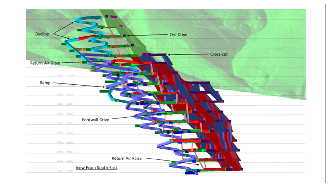
Figures 3 & 4 illustrate the planned declines, ramps, levels and stopes at Rupice. The mine design comprises largely of the access and ventilation portal areas (shown in red in Figure 3), main declines (light blue), trackless ramps (light purple) sub-level access drive (green), and the sub-level footwall drives (green).
The main ventilation infrastructure includes the return airway decline, return air drives and return air raises. The intake air will travel down the middle and lower access declines and into the mine via the internal ramps and onto the levels where it will leave the mine via the return air raises and ultimately exhausted through the upper return airway portal. The mine will operate on a “push” ventilation system initially, until the three declines are linked together, and sufficient development is complete to allow stoping to commence. At this point (scheduled to be approximately 10 months after commencement of mine development), the primary ventilation fans will be commissioned, and thereafter the mine will operate using a “pull” ventilation system.
Figure 4: Rupice Underground Mine design (view from the southeast)
Scheduling rates for Rupice are based on the activities required and the estimated cycle times for each activity in the mining cycle. The general sequencing follows geotechnical considerations for primary and secondary stope extraction, a general mining direction of “bottom-up” and the delays associated with in-stope void filling.
This underground mine operating model assumes the following underground working calendar and shift arrangements:
- 365 working days per year
- 2 working shifts per day
- 11 underground hours of shift duration
- 10.5 hrs effective hours per shift
The scheduling rates used in the development of the underground production schedule are summarised in Table 15 below. The rates have been estimated based on available shift time, cross-sectional dimensions, planned advance per blast and mining activity cycle time estimates.
The effective stoping rates are calculated based on all the activities required to establish, slot, drill and blast, muck and then fill a stope. The backfill test results indicate that slotting of the secondary stopes can safely commence 21 days after completion of backfilling in the adjacent primary stopes. The backfill costs also made provision for higher binder content to enable strong fill curing within 21 days.
Table 15: Mining cycle time estimates
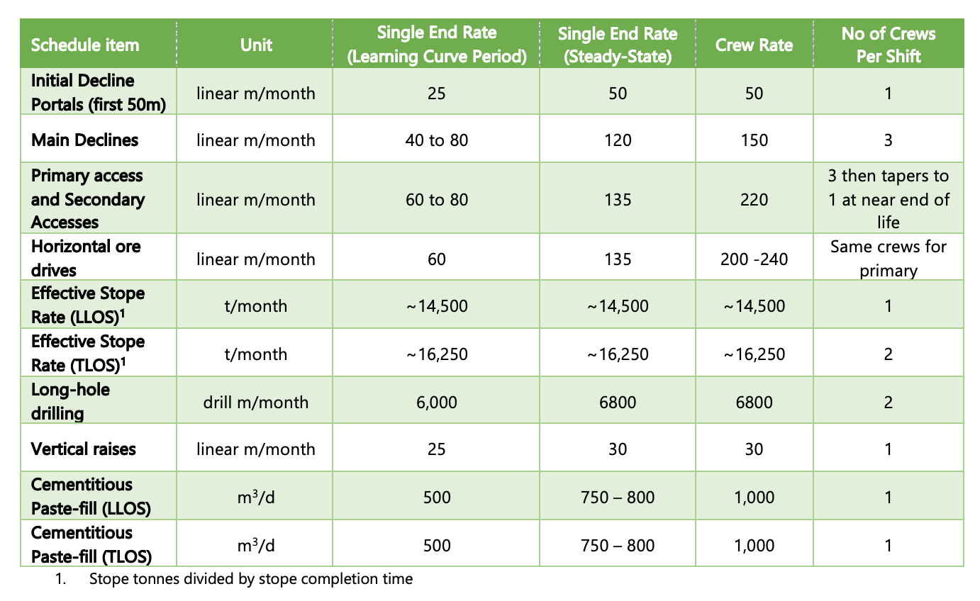
The long-hole drilling metres are calculated from the stope drill and blast designs concluded, which assume a factor of 7 tonnes of ore per blast hole. Two longhole drill rigs will be employed to do all the slotting, the smaller level ventilation rises and the stope drilling.
The mining cycle will consist of the following sequential activities:
- ore drive development
- hanging wall cable bolting
- stope slotting
- stope production drilling
- charging and blasting
- Remote-controlled stope loading
- truck loading at stockpiles
- hauling
- backfill wall installation
- backfill plug pour
- complete stope backfilling
- allow sufficient time to cure prior to starting any neighbouring stope slotting activities
Drill and Blast
The drilling activities will be separated into short-shot-hole, long-shot-hole and support drilling. Different mechanised drilling machines will be used for each of these activities. Support drilling will be performed by one cable bolt support drilling rig (bolter) capable of drilling long holes for installation of cable bolts and other ground support bolts. Short hole drilling will be performed by double boom drill-rigs (jumbos). Primary support will be a combination of friction bolts or grouted bolts and will be performed using the jumbos and bolters where required. When necessary, synthetic fibre reinforced shotcrete will be applied up to 75 mm thick for long-life access ways using a mobile shotcrete vehicle. Longhole drilling will be performed by a top hammer long-hole drilling machine capable of drilling up to 32 m to 35 m tubed long holes, 76 mm to 89 mm in diameter.
Blasting activities will be supported by charge-up crews and utility vehicles modified for the purposes of transporting explosives, blasting accessories and charging of the blast holes. The modified utility vehicles will be loaded at the surface magazines where emulsion will be sensitised and loaded into the special purpose explosives kettle located on the charge-up vehicle. A water-resistant emulsion explosive will be used in conjunction with cast boosters as a primer and shock tube detonators. Blasting will be initiated at fixed intervals at the end of the shift from a central control room once shift clearance procedures are complete. Longhole stoping blast holes will have at least two primer-boosters per hole.
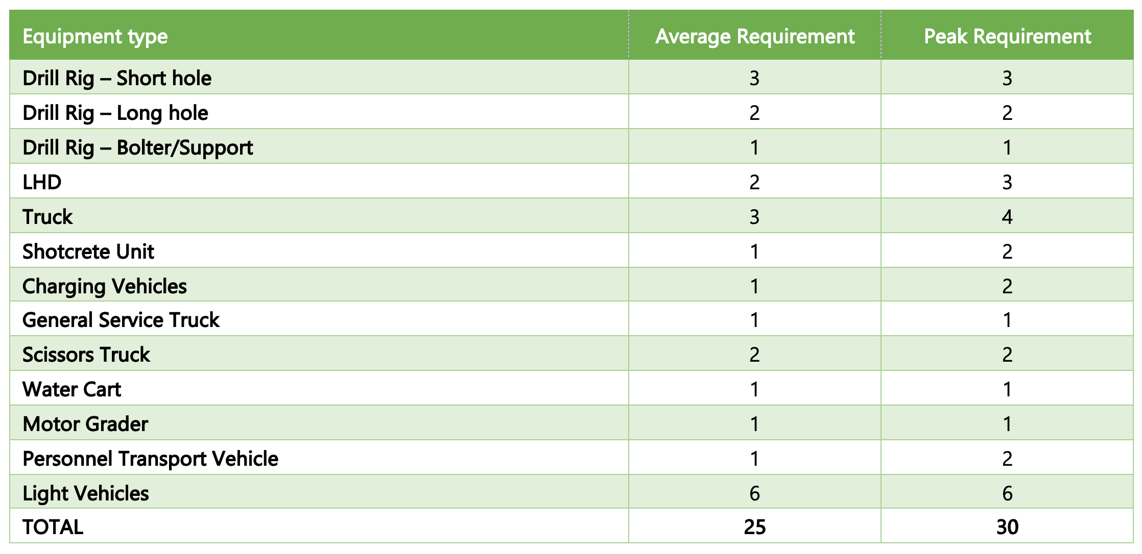
Equipment
The loading of blasted feed material and waste as well as the backfilling of the stopes will be achieved using a single type of load haul dump unit (“LHD”) model and size in order to minimise the inventory of equipment spares. Mucking of waste development, drive development and stoping materials will utilise a 14-tonne class LHD. Backfilling of waste (when available) into the open stopes will utilise the same class 14-tonne LHD, but stope backfilling will mostly try to utilise the backfill plant and system.
Transport of ore and waste to surface will be achieved by 42-tonne class diesel haul trucks via the main transport drives, ramps and declines to surface.
The ancillary equipment fleet will consist of various utility vehicles for the transport of equipment, consumables and stores in and out of the underground mine. There will also be an underground motor grader, integrated tool handler and light vehicles. The estimated mechanised mining machinery is summarised in Table 16 below.
Grade control drilling to facilitate detailed grade estimation and also geotechnical conditions, ahead of mining, will be achieved by use of a dedicated diamond drill rig. Diamond drill grade control holes will be completed, such that diamond core for detailed geological and geotechnical logging, assaying and grade estimation will be available at a minimum of three months in advance of the stoping production schedule. The grade control and geotechnical drilling is an essential and integral part of the mine production sequence.
Underground Labour
Mining operations at the Rupice Underground Mine will be based on a 12-hour shift, with staff rostered 4 days on, 4 days off, and additional staff to cover leave.
Table 17: Rupice Underground Mine Labour Requirements

The Rupice underground schedule was developed on a month-by-month basis from start to finish. The schedule is conversative as it will allow for operator learning curves and reasonable linear advance rates. This schedule is largely driven off the assumption that the mining crews will be experienced at the onset with skilled supervision to ensure the schedule progress is achieved. The initial stopes targeted allow for some stope learning and are scheduled within a couple of medium grade stopes whilst the access development progresses down to the intended high value mining block.
Geotechnical Considerations
The Rupice deposit is situated within a thrust-bound belt of Triassic rocks surrounded by Jurassic carbonates. The stratigraphy is not well defined, due to fault-related structural complexity and alteration but, in general, a footwall sandstone is overlain by marls and dolostones that host the mineralised horizon, with a hanging wall that commonly includes a laminated dolomitic mudstone.
The range of rock types vary from limestone, dolostone, calcareous and dolomitic marl, to a range of siliciclastic rocks, including cherty mudstone, siltstone, and sandstone. The mechanical properties of the rocks are weak and with extensive bedding, foliation and shearing can be considered a poor to fair ground type.
The extensive diamond drilling program has allowed a structural and ground condition model to be developed. This will assist in predicting ground conditions, allowing support standards to be developed to match ground conditions.
Primary development will be placed in the marginally better footwall ground, sufficiently far from the orebody to negate the influence of mining. The main support for the declines and ramp development will be a fibre reinforced shotcrete with a systematic bolting pattern. The thickness of the shotcrete and density of bolting will be adjusted as ground conditions change. In very poor ground, additional support measures such as mesh, arches or cables may be used.
The LLOS mining method has been selected in narrow ore sections with TLOS in the wider sections. The stopes will be relatively small to minimise open spans and a paste backfill utilised to control any ground displacements.
A strict stoping sequencing will be observed to ensure induced stresses are not created. The stopes will be pre-supported on the hanging wall and where necessary in the drill drive roof by long cable bolts. Additional cables will be installed in the extraction drives to ensure safe longhole charging. All mucking of the stopes will be done remotely. Tight backfilling of stopes will be done to prevent any back-breaks and minimise rock mass movements. A monitoring program using stress-meters and extensometers will be utilised to predict and manage any ground behaviour changes. Continuous back analysis, empirical and numerical modelling will be carried out on stoping performance to ensure that the safest optimum designs are used.