Pre-Feasibility Study - Mining
Bosnian Pre-Feasibility Study
15 October 2020
Mining
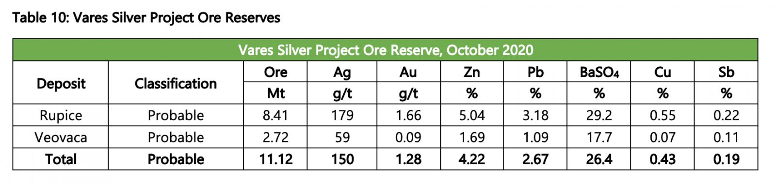
The Ore Reserve estimate was prepared by Axe Valley and comprises 11.12 Mt at 150 g/t Ag, 1.28g/t Au, 4.22% Zn and 2.67% Pb, as set out in Table 10.
The Ore Reserves for the Vares Silver Project deposits have been estimated using the JORC Code and the Ore Reserves are part of the Mineral Resource. The JORC Code defines an Ore Reserve as:
“An ‘Ore Reserve’ is the economically mineable part of a Measured and/or Indicated Mineral Resource. It includes diluting materials and allowances for losses, which may occur when the material is mined or extracted and is defined by studies at Pre-Feasibility or Feasibility level as appropriate that include application of Modifying Factors. Such studies demonstrate that, at the time of reporting, extraction could reasonably be justified.”
The Ore Reserve assumes a direct conversion between Indicated Resources and Probable Reserves.
As discussed below, the selected mining method for the Rupice deposit was underground mining, whilst the Veovaca deposit is amenable to conventional open mining methods. Conceptually, the mining recovery for both Rupice and Veovaca have been estimated at 95% and the average dilution factors for Rupice and Veovaca are 10.5% and 10% respectively.
Rupice Underground Mine
It is proposed that primary access to the underground workings will be via two parallel declines developed from surface and will be suitable for trackless equipment. Following the anticipated excavation of a box cut, the declines are anticipated to be developed with dimensions of 5.5m wide X 5.8m high and a maximum gradient of 16% (1 in 6). Generally, declines are developed at 14.3% (8.3 degrees or 1:7), but the Rupice ore body requires the portal positions to be located to enable optimal placement of mining infrastructure on surface, yet require to get to a certain mining elevation (1045 ASL) reasonably quickly to enable the development of the best value regions. The remaining declines going up and down from the different underground access positions are all developed at the 1:7 ramp inclination. All decline ramps have conceptually been positioned to minimise development required to access the initial high-grade stoping area and to provide the shortest distances to the centre of mass of each of the major stoping areas. The decline cross-section area proposed has been selected to allow for future haulage using diesel trucks of 50 tonne capacity but could also use the larger 63 tonne capacity truck option. The two main declines to surface are anticipated to allow for dedicated traffic in each direction with minimal disruption to the hauling operations. These twin declines are also the essential intake airways into the underground mine.
Internal decline ramps will be developed off the main decline at appropriate positions to allow for access to the sub-level development. The proposed ramp dimensions will be 5.2m wide X 5.2m high with a maximum gradient of 14.3% (1 in 7) and a minimum curve radius of 20m for the turns which would allow trucks from loading points on each sub-level to enter the ramp and then the main decline for transport to surface. The size of trucks and truck cycles would ensure there is not significant equipment traffic in these declines and there are several underground stockpiles and re-muck bays planned to allow for passing of equipment. The declines were also developed in a “figure of 8” geometry to allow for better visibility and to gradually follow the higher-grade zones along the strike of the orebody.
Secondary development is anticipated to consist of sub-level ramps that are driven to connect with the footwall drive on each sub-level with a minimum of 20m stand-off from the deposit (measured from the outside of the drive to the inside of the stopes. The footwall drives are proposed to have dimensions of 5m wide X 5m high.
The sub-levels will be spaced at 20m vertical intervals. Horizontal cross-cut drives, at dimensions of 5m wide X 5m high, are proposed to be developed at right angles to the strike of the deposit with the cross-cutting ore/drill drives spaced 15m apart to adequately traverse the deposit and provide for a 15m stope strike drilling envelope in a primary-secondary stope sequence and retreating back from the hanging wall to the footwall (direction). Conceptually, once the crosscut ore-drive is in its final position (just through the hanging wall contact), a 10-hole (9-holes charged) blast slot will be developed using a long-hole production drilling rig to create a free face for subsequent ring blasting (1.5 metre spaced rings) by retreat extraction. The mine design of the rings has the holes spaced to optimise drilling and to allow for a suitable Powder Factor (PF) whilst not over breaking the stopes and fracturing the surrounding secondary stope envelopes. Further to this, the mining costs allowed for the drilling of Twin-strand anchor bolts in the hanging wall in a fan shape at the ends of the ore-drives prior to the slotting being done. This will further improve the hanging wall stope stability on retreat. It is proposed that loading of the blasted material be at the intersection point of the crosscut and the footwall drive and hauled via the internal ramp and decline to surface, tipped into the primary crusher and then deposited in different stockpiles before being reloaded onto on-highway trucks for haulage to the Veovaca processing plant. Further provision has been made underground for additional temporary mine stockpiles (on the 1045 ASL) as the surface area outside the portal is limited.
Figures 1 & 2 illustrate the proposed declines, ramps, levels and stopes at Rupice. The conceptual mine design comprises largely of main declines (light pink-figure 3), trackless ramps (blue) and the sub-level footwall drives (green). The mine was sub-divided into two main divisions namely the Longitudinal Longhole Open Stoping zone (LHOS) and the Transverse Longhole Open Stoping Zone (TLHOS). The proposed LHOS zone is positioned from and above the 1,065 level and the TLHOS zone below the 1,065 level. The anticipated main ventilation infrastructure includes raise-bored shafts that are shown in the diagram below. The intake air will conceptually travel down the twin declines and into the mine via the internal ramps and onto the levels where it will leave the mine via the return air raises and ultimately exhausted through the main exhaust ventilation shaft. This will be a push ventilation system in year 1 turning into a pull ventilation system from year 2 onward.
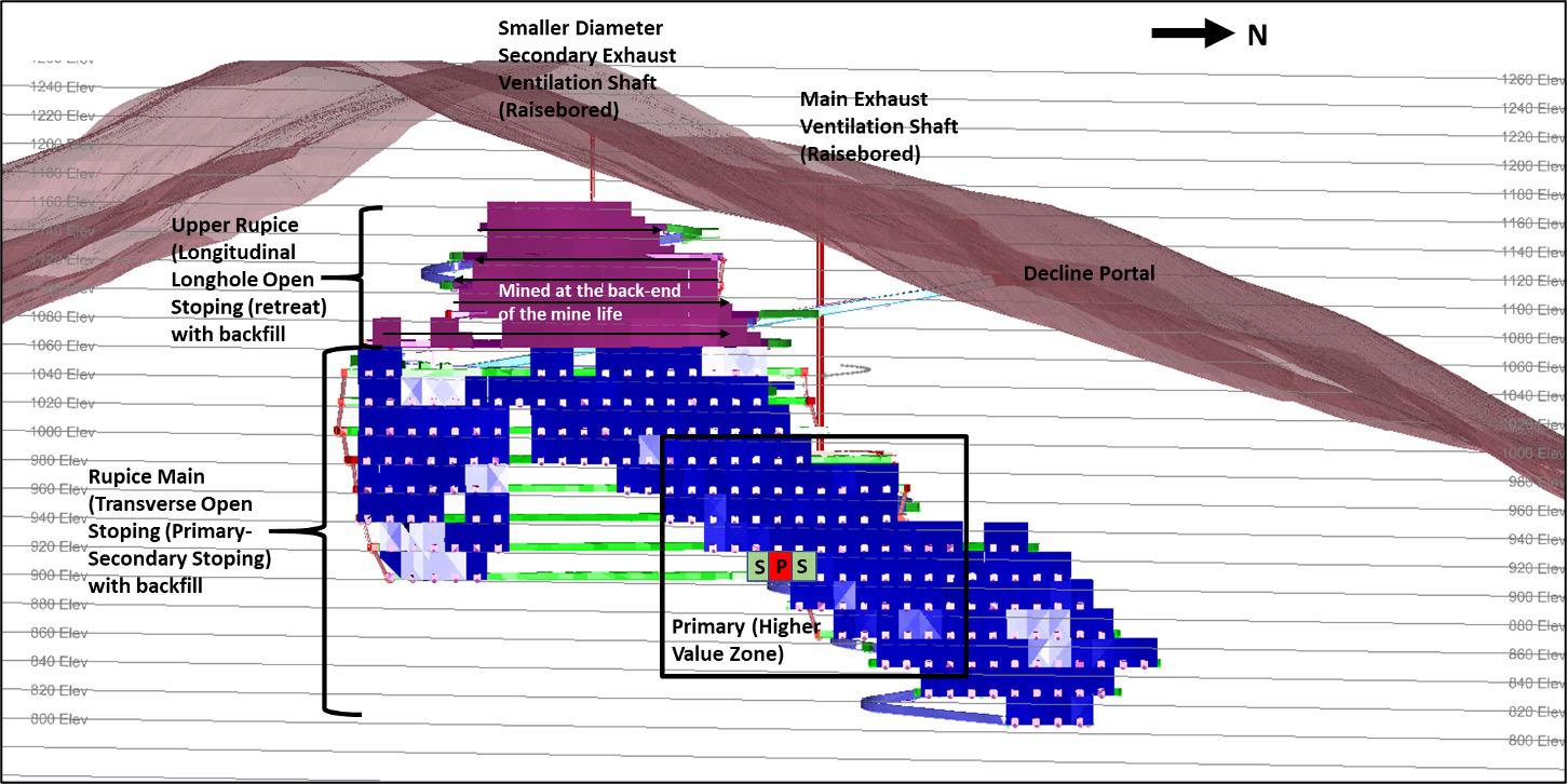
Figure 1: Mine Design (View 1)
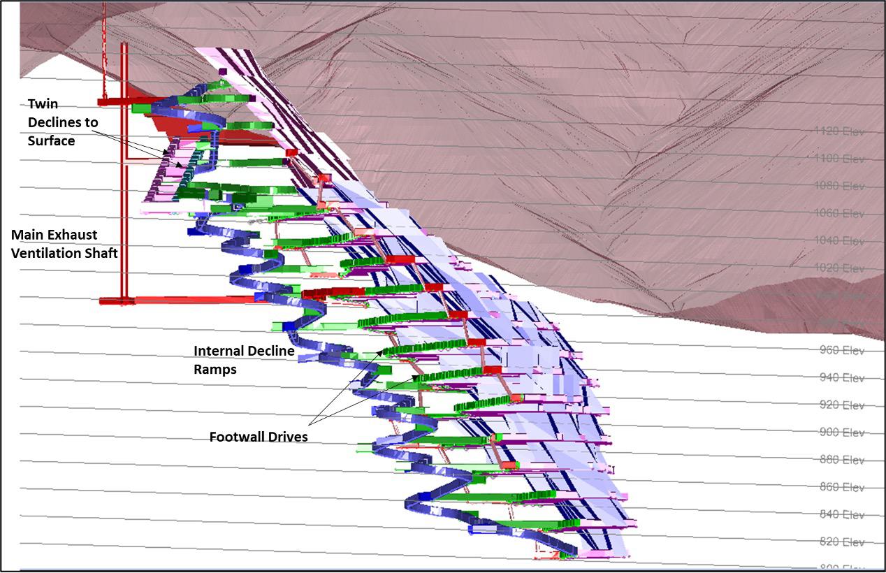
Figure 2: Mine Design (View 2)
Scheduling rates are based on the anticipated activities required and the estimated cycle times for each activity in the mining cycle. Proposed general sequencing followed geotechnical considerations for primary and secondary extraction, “bottom-up” general mining direction and delays in stope void filling.
This underground mine operating model assumes the following underground working calendar and shift arrangements:
- Working days per year – 365
- Working shifts per day – 2
- Underground shift duration, hours – 11
- Effective hours per shift – 7.8 hrs
The scheduling rates used in the development of the proposed underground production schedule are summarised in Table 11 below. The rates have been estimated based on anticipated available shift time, cross-sectional dimensions, planned advance per blast and mining activity cycle time estimates.
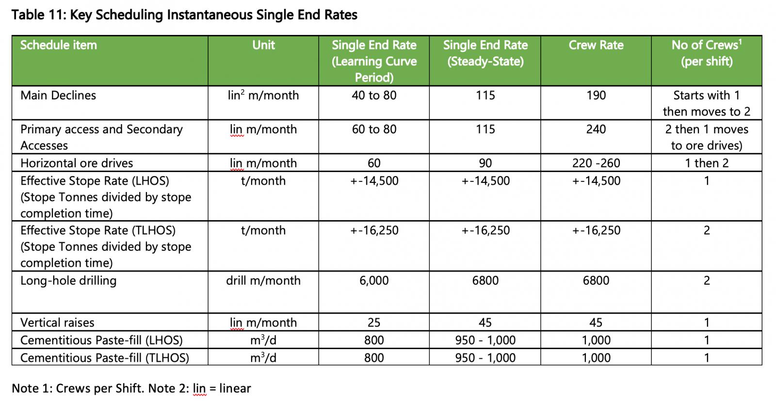
The Effective stope rates are calculated on all the activities required to establish, slot, drill and blast, muck and then fill a stope. The backfill test results indicate that the secondary stopes can commence with slotting within 14 to 16 days after backfilling of the primary stopes has taken place. The backfill costs furthermore made provision for high binder content to enable strong fill curing within 14 to 16 days. The mine scheduling still allowed for a total of 18 to 21 days post backfilling to ensure strong curing but to also allow for the development through the brow-fill to establish the next stope slot (on retreat in very wide stope zones).
The long-hole drilling metres are calculated from the stope drill and blast designs concluded (which essentially has a 7tonnes per blast hole factor). Two longhole drill rigs should be employed to do all the slotting, the smaller level ventilation holes and the stope drilling. A derived activity has been used to estimate the required fill volumes and is dependent on preceding stoping completion with an added curing delay on the fill to neighbouring stope. When a stope mines up to the sill pillar it was ensured that there be at least 40 days between the upper stopes (above a sill) to the stopes to mine the sill. Most of the stopes actually have much longer lag times than this which allows the backfill above the sill pillar to cure to its absolute full strength. Stopes above the sill pillar could also be filled with a 6.5 to 7% binder content if the geotechnical engineers believe it necessary.
The mine proposes a mechanised longhole blast-hole retreat method for stoping and trackless equipment for transport. The proposed mining cycle consists of the following key production areas:
Trackless mechanised development (drilling, supporting, blasting, loading and hauling) with the longhole open stoping comprising of the following sequential activities:
Mechanised longhole stoping
- ore drive development
- hangingwall cable bolting
- stope slotting
- stope production drilling
- charging and blasting
- remote stope loading
- truck loading at stockpiles
- hauling
- backfill wall installation
- backfill plug pour
- complete stope backfilling and
- allowing for sufficient time to cure prior to starting any neighbouring stope slotting activities
The drilling activities are separated into short shot-hole, long-shot-hole and support drilling. Different mechanised drilling machines are proposed for each of these activities. Support drilling would be performed by up to two support drilling rigs (bolters) capable of drilling long holes for installation of cable bolts and other ground support bolts. Short hole drilling would be performed by double boom drill-rigs (jumbos). Primary support of resin rebar and friction bolts may be performed using the jumbos and bolters where required. Longhole drilling is anticipated to be performed by a top hammer long-hole drilling machine capable of drilling up to 32 to 35m tubed long holes, 76mm – 102mm in diameter.
It is expected that the blasting activities will be supported by charge-up crews and utility vehicles modified for the purposes of transporting explosives, blasting accessories and charging of the blast holes. The modified utility vehicles would be loaded at the surface magazines where emulsion will be sensitised and loaded into the special purpose explosives kettle located on the charge-up vehicle. It is planned that water-resistant emulsion explosives would be used in conjunction with cast boosters as a primer and shock tube detonators. Blasting would be initiated at fixed intervals at the end of the shift from a central control room once shift clearance procedures are complete. Longhole stoping blast holes will have at least two primer-boosters per hole. It is also proposed that investigations into semi-autonomous longhole drilling be completed to further enhance drilling accuracy and safety. Drilling personnel set up the rig and stand in a safe, remote supported location during longhole drilling and therefore also improving productivity.
The loading of blasted feed material and waste as well as the backfilling of the stopes will conceptually be achieved using a single type of load haul dump unit (LHD) model and size in order to minimise the inventory of equipment spares. Mucking of waste development, drive development and stoping materials would utilise a 14-tonne class LHD.
Backfilling of waste (when available) into the open stopes would utilise the same class 14-tonne LHD, but stope backfilling will mostly try to utilise the backfill plant and system.
Transport of feed material and waste to surface is proposed to be achieved by the loading of broken rock into 50-tonne class diesel haul trucks and hauling via the main transport drives, ramps and declines to surface. The proposed cross-sectional dimensions of primary and secondary development have the potential for a 63-tonne class truck to be used at the intersection of the orebody drive and strike drive so that LHDs can load blasted rock into haul trucks for transport to surface.
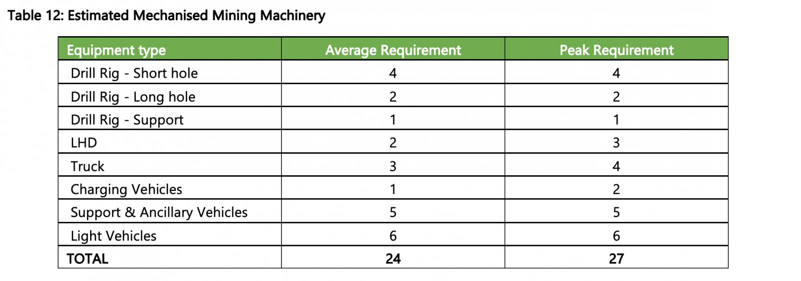
The proposed ancillary equipment fleet at Rupice Project will consist of various utility vehicles for the transport of equipment, consumables and stores in and out of the underground mine. In addition to the utility vehicle fleet, an underground motor grader, integrated tool handler and light vehicles are proposed. The estimated mechanised mining machinery is summarised in Table 12 below.
The processing plant would operate on a similar shift arrangement to the mining operations. Management, administration and technical services would operate on a 11-shift fortnight with leave allowance being covered by junior or supporting roles.
The Rupice underground schedule was developed on a month by month basis from start to finish. The schedule allowed for operator learning curves and also reasonable linear advance rates. This schedule is largely driven off the assumption that the mining crews will be experienced at the onset with skilled supervision to ensure the schedule progress is achieved. The initial stopes targeted also allows for some stope learnings and these were scheduled within a couple of medium grade stopes whilst the access development progresses down to the intended high value mining block.
Veovaca Open Pit Mine
Mining will be by conventional open pit methods, including Drill and Blast (D&B), followed by Load and Haul (L&H). D&B and L&H are anticipated to be performed on 10m benches, with selective mining of ore on 5m flitches. Where possible in the near surface weathered zone, free diggable material could be mined without requiring drilling and blasting. Ripping by bulldozers may also be employed in transitional areas to reduce the quantity of drilling and blasting required.
The envisaged scale of mining at the Veovaca Deposit is relatively small scale with a peak total material movement of approximately 4 Mtpa. The annual processing plant feed requirement target is 800 ktpa.
The conceptual mining fleet would consist of 90-tonne hydraulic backhoe excavators and 30-tonne capacity off highway articulated dump trucks. The estimated fleet size 2 x 90-tonne class excavators, 1 x Front End Loader and 15 x 30-tonne class trucks will be the peak requirement. It is not anticipated that the fleet size will vary significantly over the life of the open pit due to topography and the reference elevation. The primary mining fleet of trucks and excavators would be supported by standard open-cut drilling and auxiliary equipment.
Waste material will be hauled to the allocated waste rock dump positions to the south of the pit.
Apart from any free dig or ripping, rock fragmentation is proposed as being accomplished utilising drilling and blasting. The rigs would be supported by a stemming tractor loader backhoe (TLB), explosive delivery vehicle and several light vehicles for carrying personnel and explosive accessories.
The proposed bench height and rock type suits drill-rigs capable of drilling 89mm to 152mm diameter blast holes. Burden, spacing and sub-drill designs will be dependent on the varying material types of the deposit. A bench height of 10m, with a flitch height of 5m, have been selected to ensure selective mining of the feed material.
As part of the geotechnical optimisation of the pit, pre-split blasting is anticipated for the final walls. The pre-split blasting would reduce ground vibration and improve the final high wall condition.
Pit support equipment for the Veovaca operation is estimated to consist of a fleet of at least one each of the following: dozer, grader, fuel bowser, water bowser, hydraulic rock-breaker, front end loader and TLB. The function of this equipment would be to support the primary mining equipment by the maintenance of pit floor and haul roads, cleaning up around the excavators to prevent excessive tyre damage, secondary breakage of oversize rocks and to water-down road surfaces to suppress dust.
The majority of the plant feed material is planned to be loaded directly from the pit into the primary crusher reception bin. It has been assumed that a small buffer stockpile will be maintained at 10 % of the total monthly feed tonnage.
Ancillary equipment for the operation would consist of service trucks, tyre handlers, mobile crane, water pumps, lighting plants and light vehicles. The function of this equipment would be to support the pit equipment and maintenance workshops.
Grade control drilling and sampling is assumed to form part of the mine planning and execution to control feed definition at the Veovaca deposit. It is planned to sample the blasthole chippings during blast hole drilling in advance of the loading activity to develop a grade control model that will inform the short and medium term mine planning.
In-pit water management is assumed to primarily consist of run-off control and sumps. The de-watering infrastructure and equipment would be sized to handle ground water inflows and precipitation. The surface water handling plan would be based on diverting as much surface water as possible away from the open pit, using collection ditches and sumps, then pumping the water to a mine water pond. As the estimated pit deepens intermediate sumps may be required on the pit’s walls and on the surface between the pit and the mine water storage dam.
The proposed mining schedule has assumed that the operations work 24/7 365 days in a year, less 15 days for unscheduled delays such as high rainfall / snowfall events which may cause mining operations to be temporarily suspended.
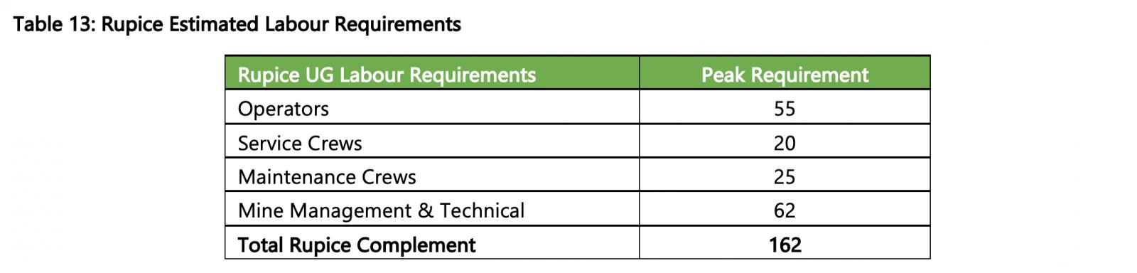
A contract mining approach has been assumed to be adopted, and an estimate of the mining contractor staff required to ensure delivery of the production mining plan estimated based on 2 x 12 hr shift for the operators, with a 3rd shift on break. The total contractor manpower will be approximately 128 full time employees.
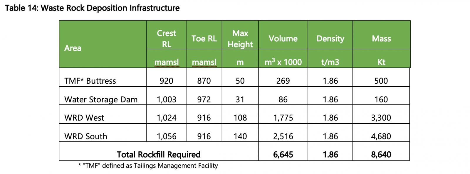
Waste rock deposition is proposed to occur in three main phases, namely:
- Pre-stripping waste used as rock-fill for infrastructure (e.g., water storage dams);
- Waste Rock Dump (WRD) West located in the valley to the immediate north of the Veovaca processing facility; and
- Long term storage on the WRD South located in the southern valley adjacent to the processing facility.
The proposed waste rock dump associated with mining operations would be constructed to meet the requirements of international best practices. Waste Rock deposition would utilise a valley fill method and provide approximately 4.5 million m3 storage capacity with a final dump profile gradient of 1:2.5. Dumps would initially be constructed with the natural fill angle of approximately 35o or the angle of repose of the dumped material. The waste dump would be progressed by tipping from a higher level against a windrow and progressively pushing the waste out with a dozer.
Conceptually, waste dumps will be progressively rehabilitated with topsoil, where possible. Surfaces of dumps would be contoured to minimise batter scour. Seepage and shallow ground water flow along the perimeter of the mine residue deposits would be controlled with suitable toe drains.
All areas impacted by the project, including all waste and tailings dumps, tailings dams and water dams would be stripped of topsoil before commencement of construction. This topsoil would be stockpiled for future rehabilitation work at the end of the mine production life.
Pre stripping the open pit to expose ore will take approximately 12 months assuming a mining material limit of 4 Mtpa. Ore mining is then proposed to start in December 2031 and would ramp up the Veovaca feed supply from April 2032 and reach steady state production in November 2032. In order to ensure a seamless “dove-tail” with the ramp-down production tail from the Rupice underground mine initial ramp-up material is proposed to be stockpiled and reclaimed during the switch-over from underground to open pit feed.