DFS - Metallurgy and Processing
Bosnian Definitive Feasibility Study
12 September 2021
The 2021 DFS process design is based on treating ore from the Rupice Underground Mine through a sequential flotation process to produce a silver-lead concentrate and a zinc concentrate. The process design is based on testwork conducted by Wardell-Armstrong, Metso-Outotec and others.
The key considerations for the selection of the process equipment included the variable nature of the orebody in terms of both feed grade and comminution characteristics, the use of equipment from reputable vendors and a minimised process plant capital cost without compromising reliability. The process design has been optimised around metal production during the first five years of operations.
Processing Modifications Since 2020 PFS
The processing optimisations have simplified the process design and significantly reduced the project execution and operational risk:
Removal of the barite concentrate recovery circuit
Market research conducted by an independent barite marketing expert concluded that, while the barite concentrate produced by the Vares Processing Plant had a suitable end-market, the current weak demand and prices of barite and the high shipping rates negatively affected its contribution to the project.
Given these findings the Company decided to remove the barite circuit, pending future improvements in its profitability. The Vares Processing Plant layout has allocated space, adjacent to the flotation building, for the future installation of a barite recovery plant and barite concentrate handling.
Not recovering the barite concentrate, reduces the project execution risk by removing 200,000 tonnes of concentrate movement in the first year of Commercial Production and 1.1 million tonnes over first 5 years.
Removal of the sulphide (pyrite) concentrate recovery circuit
The sulphide (pyrite) concentrate recovery circuit was the penultimate step in the 4-stage sequential process designed in the 2020 PFS. It was developed to remove remaining sulphide minerals from the barite concentrate. In practice, the tailings of the silver-lead recovery circuit fed the zinc circuit; the tailings of zinc circuit fed the sulphide (pyrite) circuit; and the tailings from the sulphide (pyrite) circuit fed the barite circuit.
It had been determined that there was a small market for this product as the high sulphide content was useful as a flux in smelting operations and the small quantities of contained gold, silver and zinc contents were high enough to be payable. However, when tendered for the 2021 DFS no offers were received.
Sufficient space is available in the layout of the Vares Processing Plant for the installation of the sulphide (pyrite) concentrate recovery circuit at a later date if demand returns. It would be possible to produce the sulphide (pyrite) concentrate with or without the downstream barite recovery circuit.
New comminution design reduces environmental impact at the Vares Processing Plant
The crushing plant has been redesigned as a three-stage crushing facility at the Rupice Surface Infrastructure site. The 2020 PFS comminution design has only primary crushing at Rupice with SAG and Ball Milling at the Vares Processing Plant. With the backfill plant at Rupice Surface Infrastructure requiring two different aggregates, this created an opportunity for optimisation. The crushing at the Rupice Surface Infrastructure will now be used to produce both aggregates for the backfill plant as well as the 12mm crushed ore feed for the Vares Processing Plant.
As a result, the surface-area footprint at the Rupice Surface infrastructure has been increased to accommodate the three-stage crushing plant as well as larger ROM stockpile capacity to enable greater flexibility of stockpile management and blending to improve the consistency of the feed to the Vares Processing Plant
Subsequently, the SAG mill is no longer required in the Vares Processing Plant saving considerable costs and significantly reducing noise pollution that would otherwise affect the nearby village of Tisovci.
Process Overview
The Vares Silver Project has two processing sites; the Rupice Surface Infrastructure site and the Vares Processing Plant site. The Rupice Surface Infrastructure site, which is a greenfield site, is located above the Rupice Underground Mine site and is approximately 11 km as the crow flies, or 24.5 km by road, northwest from the Vares Processing Plant.
ROM hauled to surface from the Rupice Underground Mine will be deposited onto one of three surface stockpiles based on grade, from which the ore will be reclaimed, by a front-end loader, (and trucks, depending on distance of the stockpile from the crusher feed bin) into the three-stage crushing plant feed bin. Waste rock will be processed through the same crushing plant to produce the required aggregate materials used for the backfill plant. The ore and waste rock will be processed on a batch basis through the crushing plant and the plant has been sized on this basis. Crushed ore and aggregate material will be loaded onto trucks by front-end loader and transported to the Vares Processing Plant and backfill plant, respectively. The backfill plant is within 1 km of the crushing plant and the 24.5 km haul-road connects the Rupice Surface Infrastructure Site to the Vares Processing Plant site.
Crushed ore is received at the Vares Processing Plant coarse ore hopper and conveyed to and stored in two crushed ore bins prior to the ball mill grinding circuit, which consists of a ball mill and cyclones. The cyclone overflow reports to the sequential flotation circuit, which consists of silver-lead flotation and regrinding, and subsequent zinc flotation and regrinding. The process produces two saleable concentrates (silver-lead and zinc), which are subsequently thickened, filtered, and placed in sealed and lined shipping containers for transport.
The tailings from the Vares Processing Plant reports to a thickener and pressure filter to produce filtered tailings. The resulting filtrate is returned to the Vares Processing Plant as recycled process water, increasing water efficiency and minimising makeup water requirements. The filtered tailings are then either trucked back to the Rupice backfill plant for use as backfill in the Rupice Underground Mine or trucked and placed at the Tailings Storage Facility located adjacent to the Vares Processing Plant.
At the Rupice Surface Infrastructure the filtered tailings will be stockpiled next to the backfill plant. Waste rock from the Rupice Underground Mine, crushed to –12mm will be mixed with the filtered tailings and a cement binder in the backfill plant to produce Paste Aggregate Fill (“PAF”). The PAF backfill is then pumped into the underground reticulation system. The backfill plant will also produce Cemented Aggregate Fill (“CAF”) which utilises waste rock crushed to –75mm and cement, which will be produced and trucked underground to meet mining CAF requirements.
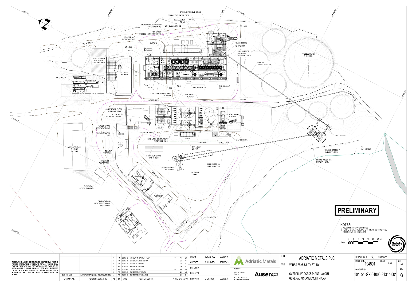
Figure 5: Vares Processing Plant Layout
Process Design Criteria
The key process design criteria for the mineral processing facilities are listed in Table 18 below:
Table 18: Process Design Criteria
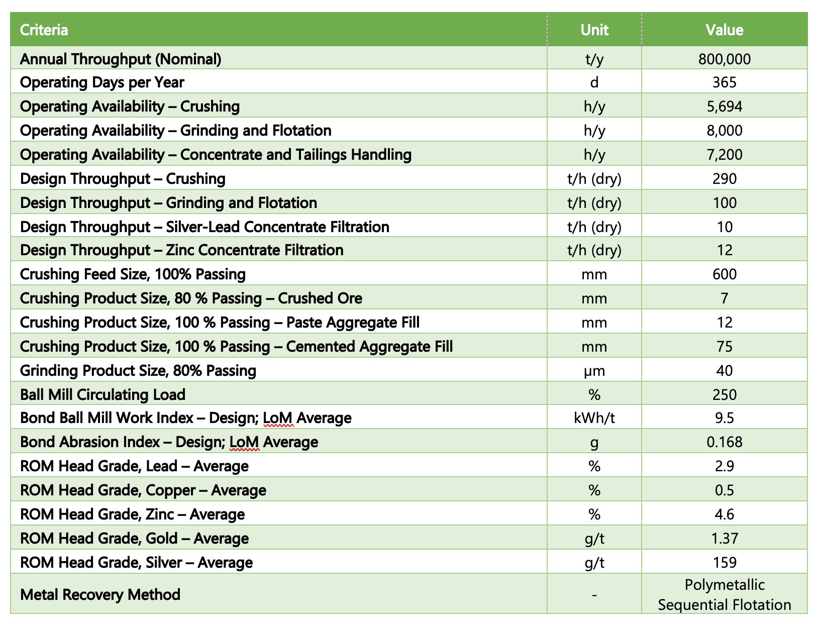
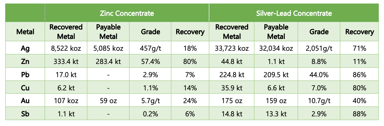
Table 19: Summary of concentrate recoveries, metal payabilities, grades and recoveries
Rupice Surface Infrastructure
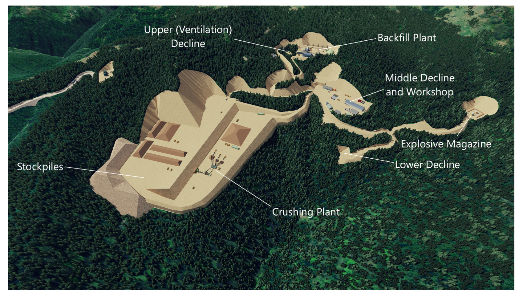
Figure 6: Isometric view of the Rupice Surface Infrastructure showing underground mine plan in red
Vares Processing Plant
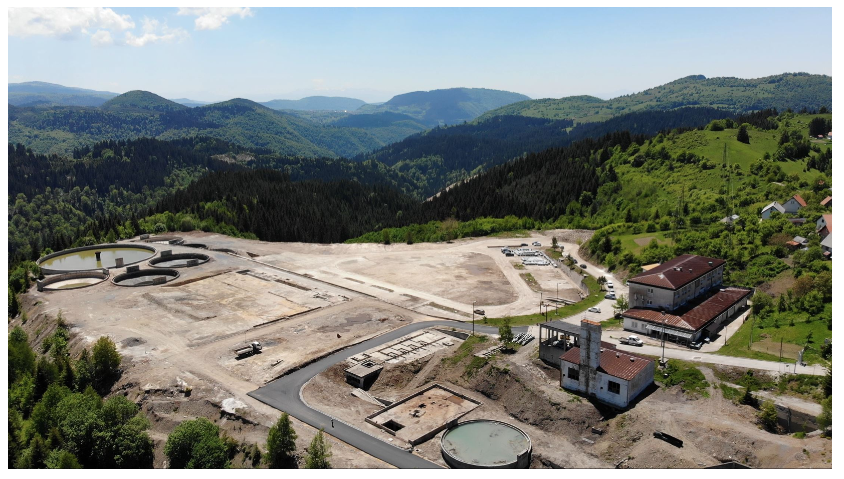
The Vares Processing Plant is located on a brownfield site. The historic surface infrastructure has already been demolished, except for the administration building and the historical tailings thickener that will be repurposed for future use, as shown on the right-hand side and left-hand side, respectively of Figure 7. Inspections have confirmed that the thickener is suitable to be re-used as the process water tank. The administration building has been in use as the Company’s offices since 2020. The new buildings can be constructed on the existing concrete pads remaining from the historical processing facilities.
Figure 7: Aerial view of the brownfield site for the Vares Processing Plant. Photo: Adriatic Metals July 2021
Process Description - Rupice Surface Infrastructure
Crushing
ROM material will be deposited by the underground trucks at one of three ROM stockpiles near the portal. The ore will be allocated to the stockpiles based on the following definitions, which are determined by reserve block NSR values;

A front-end loader will reclaim ore from the stockpiles in accordance with the blending regime required by the processing plant and deposit the ore into the blend ore bin, (crushing plant feed bin). For longer tramming distances from stockpiles the loader will load the two 30 t trucks provided and they will travel to and tip into the blend ore bin. The blend ore bin has a nominal capacity of 85 t and will be equipped with a 600 mm static grizzly to prevent oversize material from entering the crushing circuit. A vibrating grizzly feeder will feed the material from the bin to the primary crusher which will allow finer material to bypass the crusher.
The primary crusher will be a single-toggle jaw type crusher and will be designed to reduce the feed size from 80% passing 427 mm to 80% passing 150 mm. The crushed material will combine with the undersize material from the grizzly feeder which will lower the 80th percentile of the particle size distribution from 150 mm to 121 mm. The ore will then report to the secondary cone crusher which would be operated in open circuit. The secondary crushing stage would further reduce the 80% passing size of 121 mm to 51 mm. The secondary crusher discharge would then be conveyed to the triple deck sizing screen. The top, middle and lower deck screen apertures will be 75 mm, 28 mm and 12 mm respectively. Oversized material on the sizing screen decks will report to the tertiary cone crusher. The tertiary cone crusher is operated in closed circuit and will reduce the feed size from 80% passing of 50 mm to 12 mm. The tertiary crushed product is combined with the secondary crusher product prior to reaching the triple deck sizing screen. The undersize of the sizing screen provides the final product of the crushing circuit and will produce an 80% passing crushed ore product of 7mm.
The same crushing plant will also be used to produce aggregate for both PAF and CAF to the backfill plant. When producing PAF the crushing circuit will operate exactly as described above to produce the crushed ore material but will be fed with waste rock. A diverter gate system will direct the undersize of the sizing screen to a dedicated PAF stockpile that provides material with a 100% passing size of 12 mm. When producing CAF the crushing operation is truncated and will bypass the tertiary crusher closed loop circuit. The undersize of the screen will be redirected to a CAF stockpile that provides 100% passing size of 75 mm.
The crushing plant has been sized to handle the combined monthly requirements for both ore and aggregate. It will be operated on a batch basis, utilising available stockpile and coarse ore bin capacity.
Crushed ore and waste rock will rely on front-end loaders to reclaim the material and load haul trucks to be transported to either the processing plant or backfill plant, respectively.
The major equipment and facilities include:
- Feed bin (85 t capacity) with a fixed grizzly and vibrating grizzly feeder
- BRC1050 800 mm x 1045 mm Jaw Crusher
- VRS44 Secondary Cone Crusher
- VRT84 Tertiary Cone Crusher
- Triple Deck Product Vibrating Screen, VS 703-30 7m x 3m
- Crusher discharge conveyors
- Dust collection system
- Crushed ore radial stacker
Backfill Plant
The backfill plant has been designed to produce two separate products, a CAF and a PAF, throughout the mine life. During the early stages of the operation, no tailings material is available so CAF will initially be produced, before transitioning to producing both CAF and PAF once tailings material is available. The selection of the backfill product is made on a stope-by-stope basis based on the strength requirements for the mining extraction sequence.
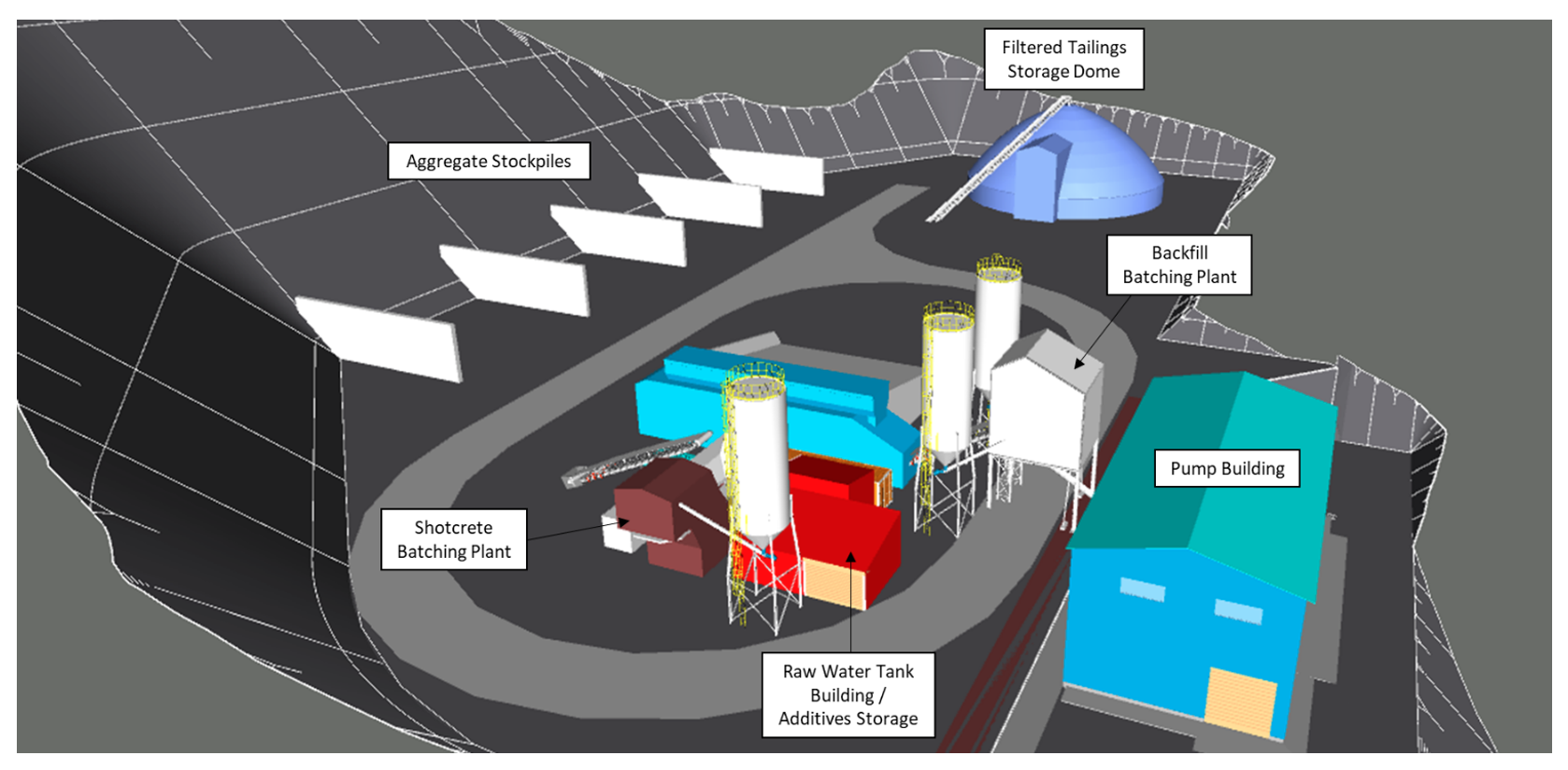
Figure 8: Backfill Plant Layout at the Rupice Surface Infrastructure site
The CAF comprises of aggregate, binder, and batch trim water. The PAF comprises aggregate, binder, processing plant tailings, and batch trim water.
Stockpiles at the backfill plant site consist of an open -75 mm aggregate stockpile (for the CAF), an open -12 mm aggregate stockpile (for the PAF), and a covered tailings stockpile (for the PAF). Aggregate is sourced from crushed development waste, whereas tailings material is trucked from the Vares Processing Plant.
Aggregate, and tailings in the case of PAF, is loaded by front-end loader to a series of weigh-hoppers that weigh and transfer the material, via a belt feeder and mixer feed conveyor, to the batch mixer in the batching plant. In the batching plant, the weighed tailings and aggregate are mixed in the batch mixer along with binder and batch trim water to generate the required product specification.
When producing CAF, material is ejected from the bottom of the batch mixer and discharged to waiting ore -haulage trucks for delivery underground as a backhaul from the ore haulage.
When producing PAF, material is ejected to a paste hopper, where it is pumped to an underground reticulation system by a positive displacement pump via two primary routes. The main route, and that for the initial phase of mining, enters the underground mine via a surface borehole near the backfill plant, which breaks through at a level of 1078 m. From there it is distributed through a series of inter-level boreholes and lateral level piping. Access to the upper stopes extracted later in the mine-life is provided via the upper ventilation decline to the 1145 m level.
The backfill plant also has a shotcrete batching and mixing system to meet underground shotcrete requirements. The plant will load the required mixture into the mixer from where it will be ejected directly into a truck for transporting underground for backfill application.
Process Description - Vares Processing Plant
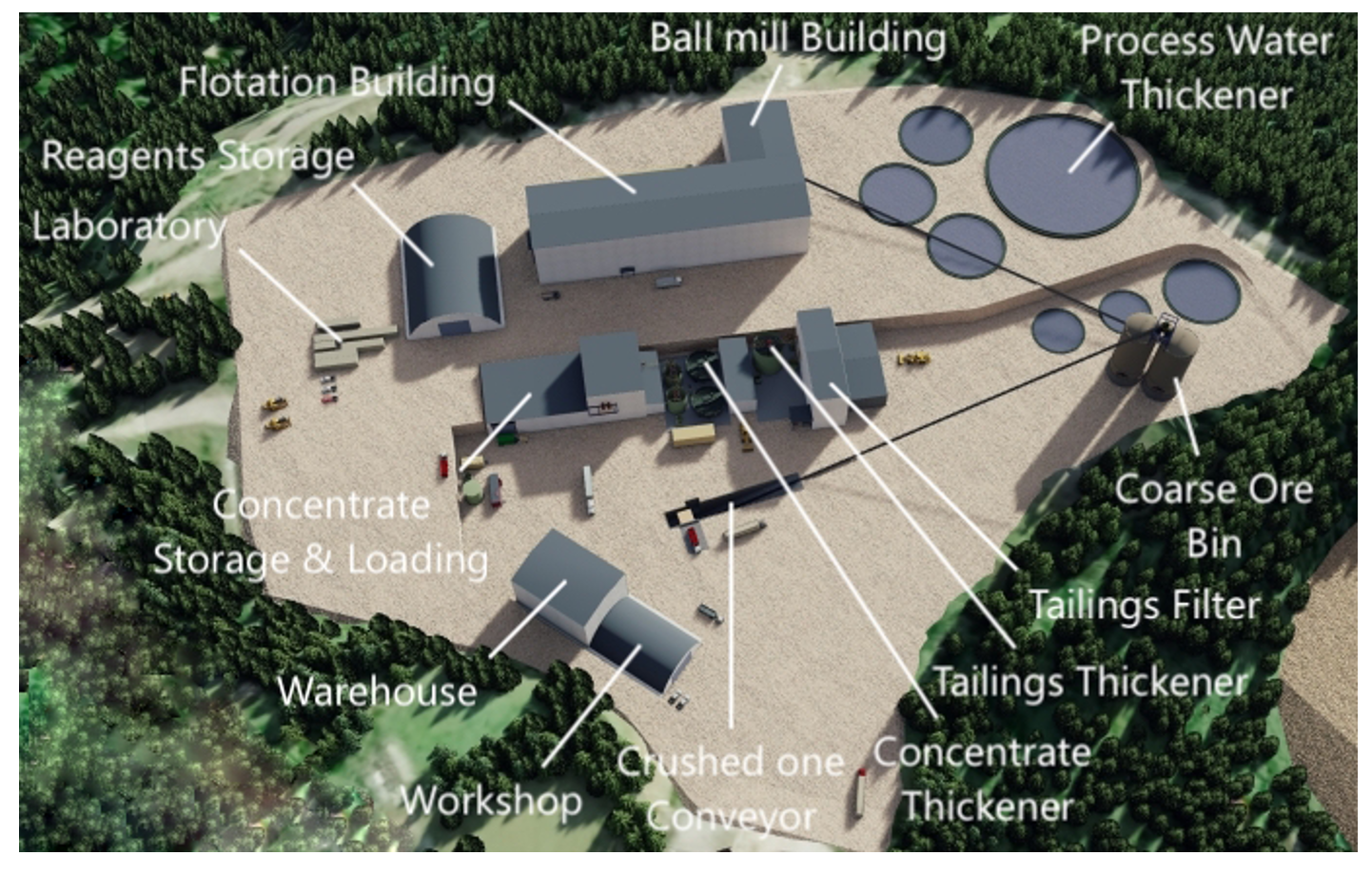
Figure 9: Isometric view of the Vares Processing Plant
Crushed Coarse Ore Handling
Crushed ore will be trucked 24.5 km from the Rupice Surface Infrastructure site to the Vares Processing Plant and end-dumped into a crushed ore hopper with a capacity of 37.5 t. The crushed ore will be fed by a belt feeder to a belt conveyor. The belt conveyor will transport the crushed ore to a diverter gate, where it will be discharged into two coarse ore bins. Each bin provides a live residence time of 23 hours and a corresponding capacity of 2,260 tonnes of ore on a wet basis. Ore will be reclaimed from the bins by belt feeders and discharged to the ball mill feed conveyor.
In the event of a process disruption, the crushed ore can be stockpiled at an adjacent coarse ore storage pad with 12 hours of storage capacity and reclaimed with a front-end loader.
The major equipment and facilities in this area include:
- 37.5 t coarse ore hopper
- 12 hour emergency stockpile
- Crushed ore bin conveyor and reversible conveyor
- Two crushed ore bins with 2,260 t capacity each (wet basis)
- Two crushed ore bin belt feeders
- Ball mill feed conveyor and weightometer
The crushed ore bins provide surge capacity between the crushing system and the ball mill and will be independently filled and discharged. The throughput to the mill will be controlled by adjusting the speed of the crushed ore bin belt feeders based on the ball mill feed conveyor weightometer output and the mill control system set-point.
Grinding
The grinding circuit consists of a ball mill and cyclones. The grinding circuit will be designed to reduce ore from an 80% passing size of 7 mm to 40 µm.
The ball mill will be a single pinion overflow mill, operating in a closed circuit. The mill has an inside diameter of 4.3 m and an effective grinding length of 7.5 m. The mill receives crushed ore and process water at a variable flow rate to achieve the correct pulp density. Lime, zinc sulphate and sodium metabisulphite (SMBS) are also dosed to the ball mill to condition the ore prior to the flotation circuit. The ball mill discharge passes over a slotted trommel screen with an aperture size of 10 mm x 25 mm. The ball mill will be charged with high chrome grinding media, ranging in diameter from 25-40 mm utilising the grinding building hoist and ball kibble.
The major equipment and facilities in this area include:
- 4.3 m diameter x 7.5 m single pinion overflow ball mill with a 2,400 kW motor
- Hydrocyclone pack and pumping system
- Grinding media handling system
Operators will monitor the grinding mills discharge density, cyclone overflow and underflow densities, power draw, cyclone pressure, and other parameters to maintain a product size of 80% passing 40 µm.
Flotation
The flotation circuit at the Vares processing plant consists of silver-lead flotation and zinc flotation circuits.
Silver-Lead Flotation
The purpose of the silver-lead flotation stage will be to recover a silver-lead concentrate. Copper mineralisation also reports to the silver-lead concentrate. The mill cyclone overflow reports to a horizontal vibrating trash screen to remove any oversize particles or material prior to flotation. The screen undersize then reports to a conditioning tank where Aerophine 3418A is added as collector. Lime, SMBS and zinc sulphate are added to the ball mill to condition the slurry pH prior to the dosing of the collector, this removes the need for a second conditioning tank. The slurry will flow by gravity to silver-lead rougher flotation at a nominal density of 40% w/w and pH 8.
Silver-Lead Rougher Flotation
The silver-lead rougher flotation cells are conventional forced air tank cells. The concentrate from the silver-lead rougher flotation cells will report to the silver-lead regrind surge tank, while the tailings report to the zinc flotation circuit. MIBC will be dosed into the feed box of the first flotation cell.
Silver-Lead Regrind Circuit
The regrind circuit consists of a cyclone cluster and stirred horizontal regrind mill operating in open circuit. Slurry from the surge tank will be pumped to the cyclones to densify the feed to the regrind mill. The overflow will target an 80% passing product size of 10 µm. The cyclone overflow reports to the silver-lead cleaner circuit, while the underflow flows by gravity to the regrind mill. The regrind mill uses ceramic media with a 2-3 mm diameter and mill discharge also reports to the silver-lead cleaner circuit.
Silver-Lead Cleaner Flotation
The silver-lead cleaner circuit consists of three sequential stages of cleaning. The first stage will be dosed with Aerophine 3418A and MIBC to promote concentrate recovery. The flotation concentrates flow from the first stage through to the third and concentrate from the third stage reports to the silver-lead concentrate thickener. The tailings flow counter-current to the concentrate, and first cleaner tailings report to the zinc cleaner flotation circuit, bypassing the zinc rougher flotation step.
The major equipment and facilities in the silver-lead flotation area include:
- Four 20 m3 rougher cells
- Four 10 m3 cleaner 1 cell
- Two 10 m3 cleaner 2 cells
- One 20 m3 cleaner 3 cells
- 1500 kW ISAMill
- Silver-lead regrind cyclone cluster
Zinc Flotation
The purpose of the zinc flotation circuit will be to recover a zinc concentrate. Tailings from the silver-lead flotation circuit report to two conditioning tanks prior to the zinc circuit, where lime, copper sulphate and SIPX are added. The conditioned slurry will be then pumped to the zinc rougher cells at a nominal density of 40% w/w and pH 9. The zinc flotation circuit follows the same arrangement as the silver-lead circuit, described as follows.
Zinc Rougher Flotation
The zinc rougher flotation cells are conventional forced air tank cells. The concentrate from the zinc rougher flotation cells report to the zinc regrind surge tank, while the tailings report to the zinc rougher scavenger cells. The scavenger concentrate also reports to the zinc regrind surge tank, while the tailings report to the final tailings thickener. MIBC will be dosed into the feed box of the first flotation cell of each bank.
Zinc Regrind Circuit
The regrind circuit consists of a cyclone cluster and stirred horizontal regrind mill operating in open circuit. Slurry from the surge tank will be pumped to the cyclones to densify the feed to the regrind mill. The overflow will target an 80% passing product size of 20 µm. The cyclone overflow reports to the zinc cleaner circuit, while the underflow flows by gravity to the regrind mill. The regrind mill uses ceramic media with a 2-3 mm diameter and the mill discharge also reports to the zinc cleaner circuit.
Zinc Cleaner Flotation
The zinc cleaner circuit consists of three sequential stages of cleaning. The first stage will be dosed with SIPX and MIBC to promote concentrate recovery. The flotation concentrates flow from the first stage through to the third and concentrate from the third stage reports to the zinc concentrate thickener. The tailings flow counter-current to the concentrate, and tailings from the first stage reports to the final tailings thickener.
The major equipment and facilities in the zinc flotation area include:
- Four 30 m3 rougher cells
- Four 20 m3 cleaner 1 cell
- Two 20 m3 cleaner 2 cells
- One 30 m3 cleaner 3 cells
- One 30 m3 cleaner scavenger cells
- 500 kW ISAMill
- Zinc regrind cyclone cluster
Concentrate Handling
The concentrate handling circuit consists of thickening and filtration equipment to dewater the silver-lead and zinc concentrates prior to loadout and shipment.
Each concentrate stream reports to a dedicated high-rate thickener, where Magnafloc 10 will be added to assist in the settling of the solids. The thickener overflows report to the process water tank, while the underflows report to dedicated filter feed tanks which have a residence time of 12 hours.
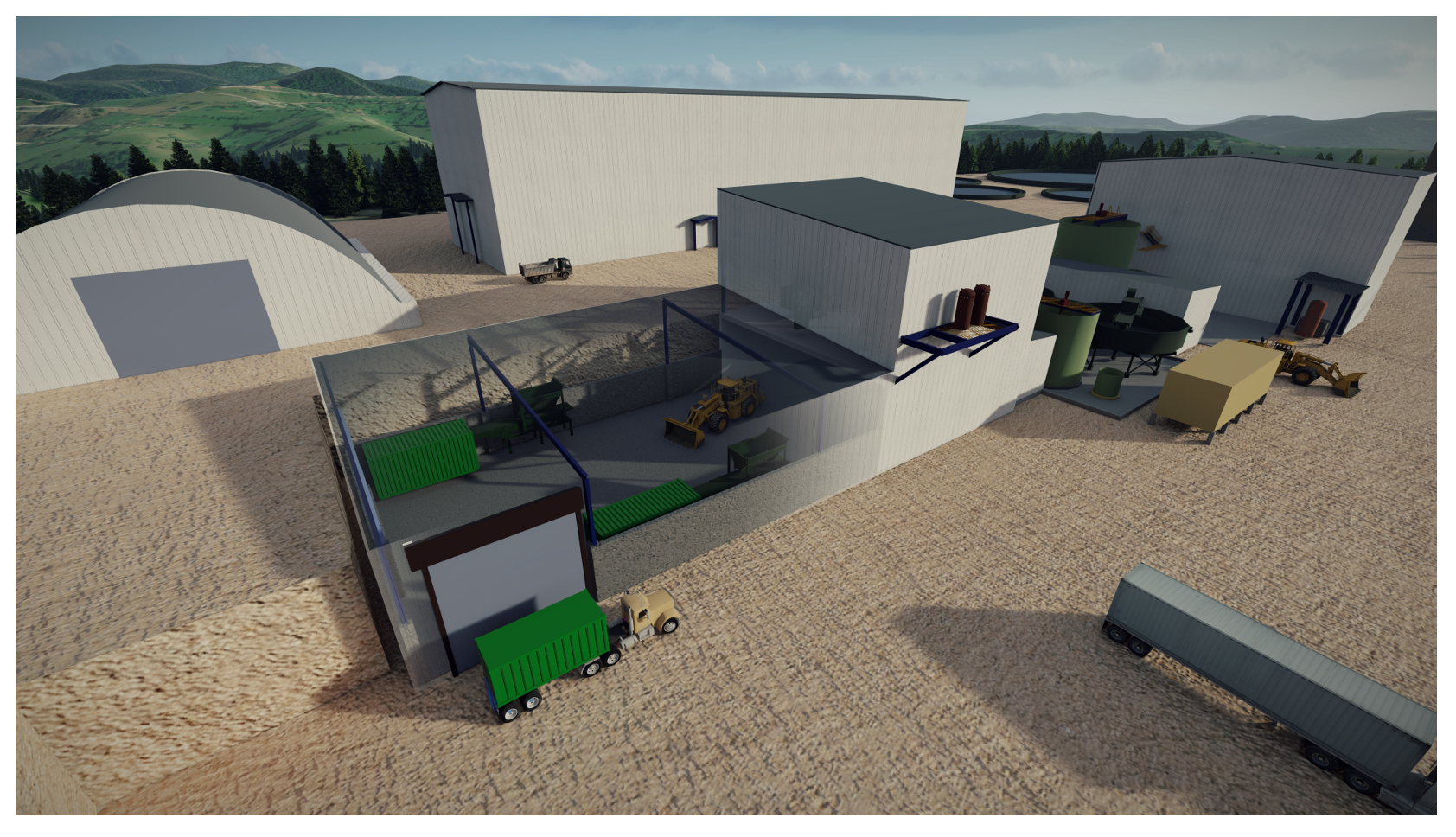
Figure 10: Isometric view of concentrate thickening and handling building
The silver-lead and zinc thickener underflows each report to a dedicated concentrate filter at nominally 65% w/w solids. The filter will be a vertical tower filter press and discharges filter cake at a target moisture content of 8.1% w/w and 9.4% w/w for the silver-lead and zinc concentrates, respectively. The filter discharges to two indoor stockpiles; one for the silver-lead concentrate and one for the zinc concentrate, each with a 12-hour storage capacity.
The concentrates are reclaimed from the stockpiles by a front-end loader and loaded into a hopper and conveyor feeding system to fill the shipping containers. The containers are stacked by a forklift outdoors, and subsequently loaded onto trucks. The Vares Processing Plant site has sufficient storage capacity for 4 days of production from each concentrate. The major equipment and facilities in this area include:
- 10 m diameter high-rate elevated tank zinc concentrate thickener
- 10 m diameter high-rate elevated tank silver-lead concentrate thickener
- Filter feed tank agitators
- Larox PF 25/35 M15, recessed-plate diaphragm, horizontal chambers filter for silver-lead filtration
- Larox PF 30/35 M15, recessed-plate diaphragm, horizontal chambers filter for zinc filtration
- Flocculant dosing system
- Conveyors to stockpiles and for loading containers
- Outdoor storage areas for concentrate containers
The thickener performance will be controlled to achieve the target underflow densities required for filtration. The filter cycle times will be adjusted as necessary to achieve the required filter cake moistures.
Tailings Handling
Tailings from the flotation circuits reports to a tailings thickener, where flocculant will be added to promote settling of the solid particles. The overflow reports to the process water tank, while the underflow reports to a filter feed tank at 65% w/w solids. The filter feed tank has a residence time of 12 hours and feeds a horizontal plate and frame pressure filter. The press produces a filtered tailings product at a target moisture content of 9.3% w/w and discharges it to a covered stockpile. The tailings are recovered by a front-end loader and transported by haul truck back to the Rupice Surface Infrastructure for use as backfill or deposited at the nearby Tailings Storage Facility (“TSF”).
The major equipment and facilities in this area include:
- Larox FFP 1516 65/70 M60, recessed-plate diaphragm, vertical chambers filter for tailings filtration
- 13m diameter high-rate elevated tank tailings thickener
- Filter feed tank agitator
- Ancillary equipment including pump boxes, pumps, and compressors
- Flocculant dosing system
The thickener performance will be controlled to achieve the target underflow densities required for filtration. The filter cycle times will be adjusted as necessary to achieve the required filter cake moistures for transport to the Rupice Surface Infrastructure site during underground operation or for the TSF.
Reagents Handling and Storage
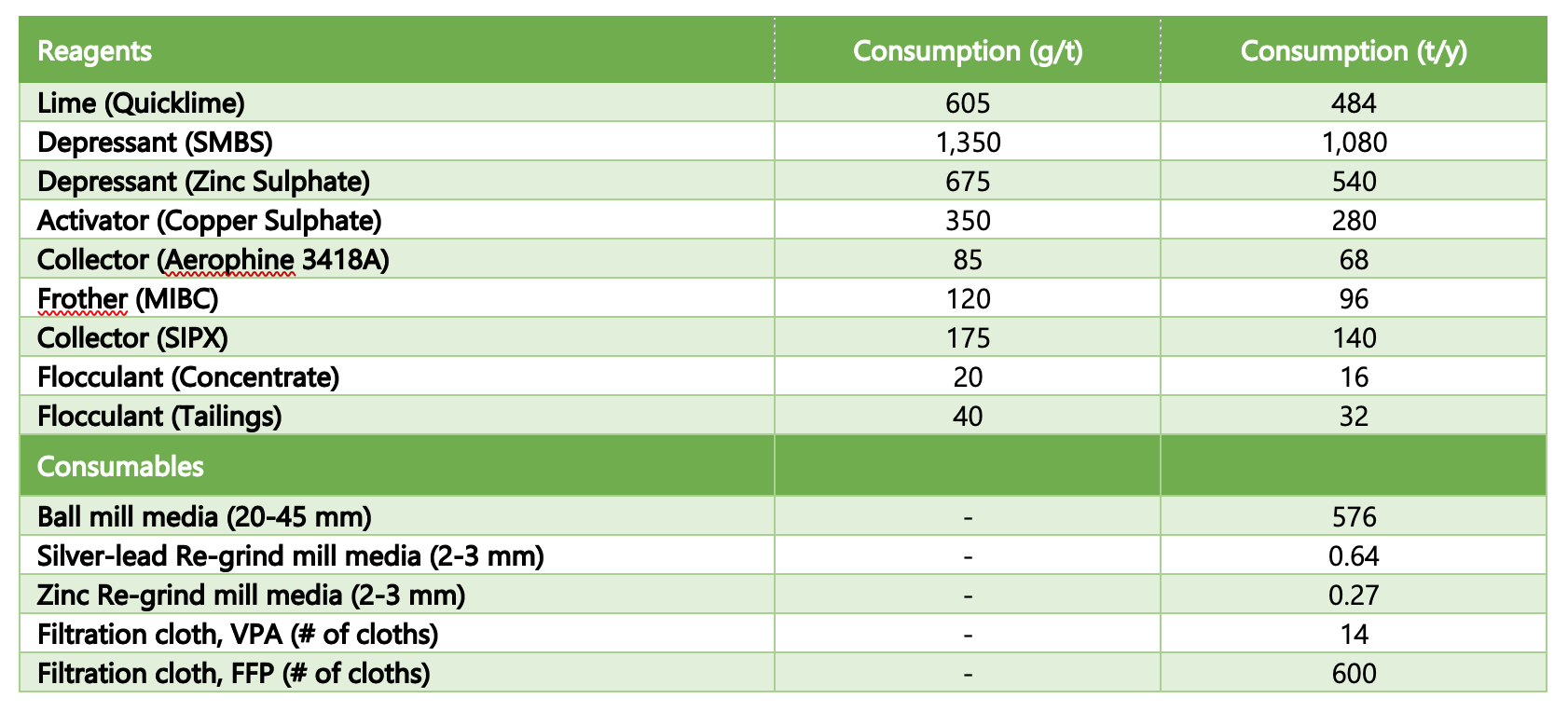
The reagents and operating consumables used in the process are summarised in Table 20 on the basis of a nominal 800,000 tonnes per year mill throughput and averaged over the LOM for Rupice ore. Reagent and consumable consumption rates were derived from test work. The Vertical Plate Pressure Filter (“VPA”) and Fast-opening Filter Press (“FFP”) filtration cloth consumption is based on an expected cloth life of 6,000 and 3,000 cycles, respectively.
Table 20: Schedule of Process Reagents and Operating Consumables
Plant Services
Services at the Vares Processing Plant include process water, raw water, fire water, potable water, gland water, and low and high pressure air services. The existing 50 m diameter tailings thickener will be used to store process water.